


Latest Products
19
2016
03
SAMSUNG DIGITAL CAMERA
1 SCOPE
This Standard covers pressure–temperature ratings, materials, dimensions, tolerances, marking, and testing for operating line blanks in sizes NPS 1⁄2 through NPS 24 for installation between ASME B16.5 flanges in the 150, 300, 600, 900, 1500, and 2500 pressure classes.
2 GENERAL
2.1 Definitions
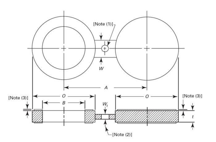
2.1.1 Figure-8 Blank.
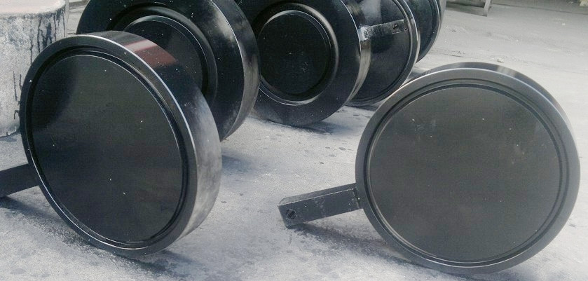
A figure-8 blank (also called a spectacle blank) is a pressure-retaining plate with one solid end and one open end connected with a web or tie bar (see Fig. 1).
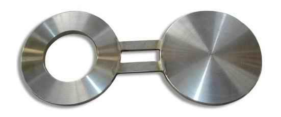
ASME B16.48 Figure-8 Blank
2.1.2 Paddle Blank.
A paddle blank is similar to the solid end of a figure-8 blank. It has a plain radial handle. It is generally used in conjunction with a paddle spacer in large sizes.
ASME B16.48 Paddle Blank
2.1.3 Paddle Spacer.
A paddle spacer is similar to the open end of a figure-8 blank. It has a plain radial handle. It is generally used in conjunction with a paddle blank.
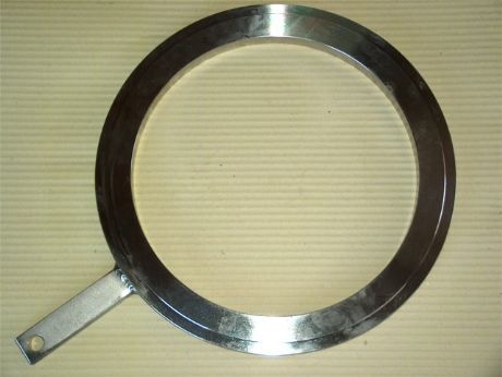
ASME-B16.48-Paddle-Spacer
2.2 References
Codes, standards, and specifications, containing provisions to the extent referenced herein, constitute requirements of this Standard. These reference documents are listed in Mandatory Appendix II.
2.3 Quality Systems
Nonmandatory requirements relating to the product manufacturer’s Quality System Program are described in Nonmandatory Appendix A.
2.4 Relevant Units
This Standard states values in both Metric and U.S. Customary units. These systems of units are to be regarded separately as standard. Within the text, the U.S. Customary units are shown in parenthesis or separate tables. Refer to Mandatory Appendix I.
The values stated in each systemare not exact equivalents; therefore, it is required that each system of units be used independently of the other. Combining values from the two systems constitutes nonconformance with the Standard. Mandatory Appendix I provides dimensions in U.S. Customary units. 1
2.5 Convention
For the purpose of determining conformance with this Standard, the convention for fixing significant digits where limits and maximum and minimum values are specified, shall be rounded as defined in ASTM Practice E 29. This requires that an observed or calculated value shall be rounded off to the nearest unit in the last right-hand digit used for expressing the limit. Decimal values and tolerances do not imply a particular method of measurement.
2.6 Size
NPS, followed by a dimensionless number, is the designation for nominal blank size. NPS is related to the reference nominal diameter, DN, as defined in ISO 6708. The relationship is typically as follows:
2.7 Service Conditions
Criteria for selection of materials suitable for particular fluid service are not within the scope of this Standard.
3 PRESSURE–TEMPERATURE RATINGS
3.1 Pressure Classes
Line blanks covered by this Standard are for the following pressure classes: 150, 300, 600, 900, 1500, and 2500 as listed in ASME B16.5.
3.2 Pressure–Temperature Ratings
3.2.1 Ratings.
Ratings are the maximum allowable working gage pressure at the temperature shown in Tables 2 and II-2 of ASME B16.5 for the appropriate material and pressure class. For intermediate temperatures, linear interpolation between temperatures within a pressure class is permitted by ASME B16.5.
3.2.2 System Pressure Testing.
Line blanks may be subjected to system tests at a pressure not to exceed1.5 times the 38°C (100°F) rating rounded off to the next higher 1 bar (25 psi) increment. Testing at any higher pressure is the responsibility of the user, taking into account the requirements of the applicable code or regulation.
3.2.3 Mixed Material Joints.
Should either the two flanges or the line blank in a flanged line blank assembly not have the same pressure-temperature rating, the rating of the assembled joint at any temperature shall be the lower of the flange or line blank rating at that temperature.
4 DESIGN
4.1 Handle
The handle orweb (tie bar) may be integral or attached to the line blank or spacer. The web and its attachment shall be capable of supporting the weight of the blank or spacer in all orientations without permanent deformation to the web.
4.2 Edge Preparation
In addition to machining, flame, plasma, saw cutting, or press punching are acceptable methods for forming the inside and outside diameters of line blanks. Surfaces shall be free of projections that would interfere with gasket seating.
4.3 Facing
4.3.1 Raised Face Joint Blanks.
The gasket seating surface and dimensions for line blanks used with raised face flanges shall be in accordance with ASME B16.5. A raised facemay be specified for these blanks at the option of the purchaser. The height of the raised faces shall be in addition to the thicknesses, t, listed in Tables 1 through 6 (Tables I-1 through I-6 in Mandatory Appendix I).
4.3.2 Female Ring-Joint Blanks.
Female ring-joint grooves shall be shaped with the groove side wall surface finish not exceeding 1.6 mm (0.63 in.) Ra roughness. The finish of the gasket contact faces shall be judged by visual comparison with Ra standards (see ASME B46.1) and not by instruments having stylus tracers and electronic amplification.
4.3.3 Male Ring-Joint Blanks.
The gasket shape (ring) for male ring-joint blanks shall not exceed 1.6 mm (0.63 in). Raroughness. The finish of the gasket contact faces shall be judged by visual comparison with Ra standards (see ASME B46.1) and not by instruments having stylus tracers and electronic amplification.
5 DIMENSIONS
5.1 General
Dimensions shall be in accordance with Tables 1 through 18 (Tables I-1 through I-18 of Mandatory Appendix I).
5.2 Tolerances
5.2.1 Facing Tolerances.
Tolerances for facings shall be in accordance with ASME B16.5.
5.2.2 Thickness Tolerances.
Thickness tolerances are NPS 18 and smaller −zero + 3.0 mm (0.12 in.) NPS 20 and larger −zero + 4.8 mm (0.19 in.)
5.3 Openings
(a)For NPS 1⁄2, NPS 3⁄4, and NPS 1 blanks in all raised face classes, the inside diameter is equal to standard weight welding neck flange bore.
(b) For NPS 11⁄4 and larger blanks in Classes 150 and 300 raised face, the inside diameter is equal to the pipe outside diameter.
(c) For NPS 11⁄4 and larger blanks in Classes 600 and 900 raised face, the inside diameter is equal to Schedule 10S welding neck flange bore.
(d) For Class 1500 raised face blanks, the inside diameter is equal to Schedule 40 welding neck flange bore.
(e) For Class 2500 raised face blanks, the inside diameter is equal to Schedule 40 through NPS 6, Schedule 60 for NPS 8 and NPS 10, and Schedule 80 for NPS 12.
(f) For all ring-joint blanks, the inside diameter is equal to the pipe outside diameter.
(g) Dimensions are based upon concentric installation of spiral wound gaskets with inner rings as required by ASME B16.20 and conform to the maximum permitted bore of ASME B16.5 welding neck flanges described in Table 16 of ASME B16.20.
5.4 Facing Finish
Facing finish shall be in accordance with ASME B16.5, para. 6.4.5.
6 MATERIALS
6.1 General
Materials for line blanks shall be in accordance with ASME B16.5, Table 1A, and shall include material restrictions cited in notes to Tables 2 or II-2 of ASME B16.5. Recommended bolting materials for flange-blank assemblies are listed in ASME B16.5, Table 1B. For materials manufactured to editions of the material specification other than those listed in Appendix III of ASME B16.5, refer to para. 6.2. Criteria for the selection of materials are not within the scope of this Standard.
6.2 Materials Manufactured to Other Editions
Materials may meet the requirements of material specification editions other than those listed in Appendix III of ASME B16.5, provided
(a)the materials are the same specification, grade, type, class, alloy, and heat-treated condition, as applicable
(b) the line blank manufacturer certifies that the requirements of the edition of the specification listed in Appendix III of ASME B16.5 have been met
7 MARKING
7.1 General
(a)Line blanks shall be marked as follows:
1.manufacturer’s name or trademark
2.material, specification, and grade or class
3.pressure class
4.B16
5.size (NPS)
6.ring number (if applicable)
(b) Where space does not permit all of the above markings, they may be omitted in the reverse order given in para. 7.1(a).
(c) The B16 designation may be applied only when the line blank has been manufactured in full conformance with this Standard.
7.2 Marking Method
The marking shall be applied by steel stamping or other marking device that leaves a legible imprint. When marking on the blind portion of the blanks, low stress marking shall be used and shall not impinge on the gasket seating surface.
8 PADDLE BLANK AND SPACER IDENTIFICATION
8.1 Paddle Handles
In order to differentiate between an installed paddle spacer and a paddle blank, it is required that there be an externally visible distinction between the two as required by paras. 8.2 and 8.3.
8.2 Paddle Blank Handles
Handles for paddle blanks shall be solid with no openings.
8.3 Paddle Spacer Handles
Handles for paddle spacers shall have a single through indicator hole located near the end of the handle. The hole diameter shall not be less than 12 mm (1⁄2 in.).
9 TESTING
Line blanks are not required to be pressure tested.
ASME B16.48 Spectacle Flanges Dimensions

as a leading manufacturer,stockist and supplier, our knowledgeable and experienced technical team can understand well
what you need . help you find the best solution for your regular and specific requirement.
contact us
“Serving the world flowing! Aiming to be the best in the field! Improving level of “Made in China”!”